
VPN Concentrator Deployment Guide
Overview
In order to connect AutoVPN sites to a central location, such as a datacenter, MX WAN appliances can be deployed to serve as a VPN concentrator. This guide outlines the configuration and deployment steps necessary for setup.
Key Concepts
Before deploying a one-armed VPN concentrator, it is important to understand several key concepts.
Operating Mode
All MXs can be configured in either Routed or VPN concentrator mode. There are important considerations for both modes. More detailed information on concentrator modes, click here.
One-Armed Concentrator
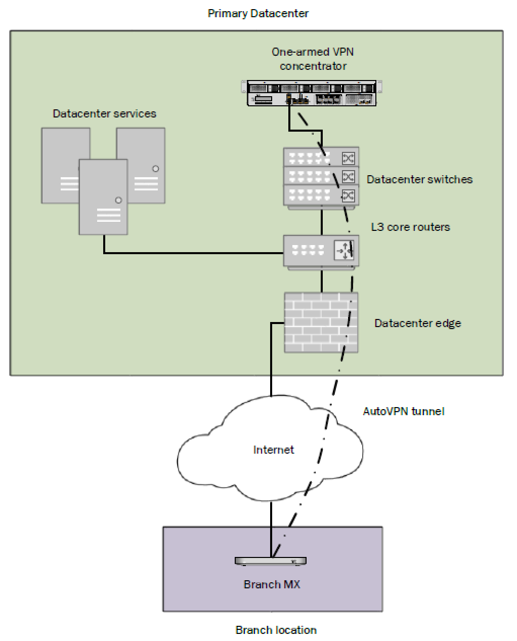
This configuration utilizes an MX device configured to act in VPN concentrator mode, with a single Ethernet connection to the upstream network. All traffic will be sent and received on this interface. This is the recommended configuration for MX appliances serving as VPN termination points into the datacenter.
Routed Mode Concentrator
In this mode the MX is configured with a single Ethernet connection to the upstream network and one Ethernet connection to the downstream network. VPN traffic is received and sent on the WAN interfaces connecting the MX to the upstream network and the decrypted, unencapsulated traffic is sent and received on the LAN interface that connects the MX to the downstream network.
Warm Spare (High Availability) for VPN concentrators
When configured for high availability (HA), one MX serves as the primary unit and the other MX operates in a spare mode. All traffic flows through the primary MX, while the spare operates as an added layer of redundancy in the event of failure.
Failover between MXs in an HA configuration leverages VRRP heartbeat packets. These heartbeat packets are sent from the Primary MX to the Spare MX via the singular uplink for MXs operating in VPN concentrator mode in order to indicate that the Primary is online and functioning properly. As long as the Spare is receiving these heartbeat packets, it functions in the passive state. If the Spare stops receiving these heartbeat packets, it will assume that the Primary is offline and will transition into the active state. In order to receive heartbeats in a one-armed concentrator configuration, both VPN concentrator MXs should have uplinks on the same subnet within the datacenter.
For Routed mode configurations, both concentrators must be able to communicate using the LAN ports. More information on Routed mode warm spare can be found here.
Only one MX license is required for the HA pair, as only a single device is in full operation at any given time.
Connection Monitor
Connection monitor is an uplink monitoring engine built into every MX WAN appliance. The mechanics of the engine are described in this article.
SSID Tunneling to an MX VPN Concentrator
The MX WAN appliance is the ideal solution for SSID Tunneling using VPN concentration as it is custom built for mission critical networks. Choose the MX WAN appliance that is best fit for your needs based on the Sizing Guide.
The WAN appliance is ready to concentrate SSIDs out of the box without any additional configuration beyond what is outlined in the quick start guide.
For additional information on how to set this up, please refer to this section.
To increase reliability, a second MX WAN appliance can be paired in HA mode. In the case that the primary WAN appliance becomes unreachable from the Meraki Cloud, the Access Points will failover to the HA standby WAN appliance.
Deploying a One-Armed Concentrator
Example Topology
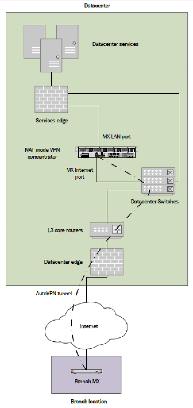
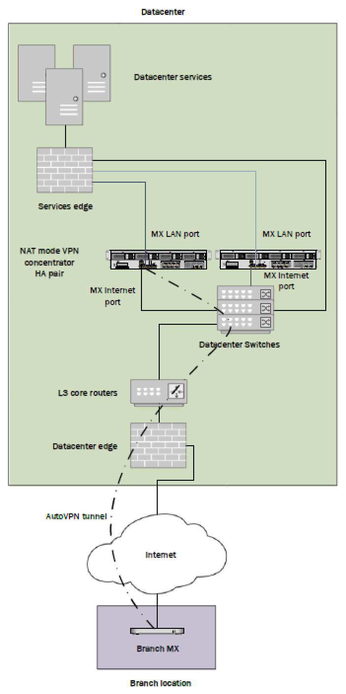
A one-armed concentrator is the recommended datacenter design choice for VPN concentration into the datacenter. The following diagram shows an example of a datacenter topology with a one-armed concentrator:
Interface Configuration
The MX WAN appliance being configured as a one-armed VPN concentrator should be connected to the upstream datacenter infrastructure using its Internet port, or using the Internet 1 port on devices models with two Internet uplink ports.
When using the MX as a one-armed VPN concentrator for VPN endpoints, be sure to not connect anything to the MX's LAN ports. If the MX is simply being used as a passthrough device, using its LAN ports will not impact its performance.
MX IP Assignment
In the datacenter, an MX WAN appliance can operate using a static IP address or an address from DHCP. MX appliances will attempt to pull DHCP addresses by default. It is highly recommended to assign static IP addresses to VPN concentrators.
Static IP assignment can be configured via the device local status page.
The local status page can also be used to configure VLAN tagging on the uplink of the MX. It is important to take note of the following scenarios:
- If the upstream port is configured as an access port, VLAN tagging should not be enabled.
- If the port upstream is configured as a trunk port and the MX should communicate on the native or default VLAN, VLAN tagging should be left as disabled.
- If the port upstream is configured as a trunk and the MX should communicate on a VLAN other than the native or default VLAN, VLAN tagging should be configured for the appropriate VLAN ID.
Public IP assignment
Placing an MX appliance configured as a one-armed VPN concentrator at the perimeter of the network with a publicly routable IP address is not recommended and can present security risks. As a best practice, one-armed concentrators MX appliances should always be deployed behind an edge firewall that filters inbound connections.
Dashboard Configuration
The Cisco Meraki Dashboard configuration can be done either before or after bringing the unit online.
-
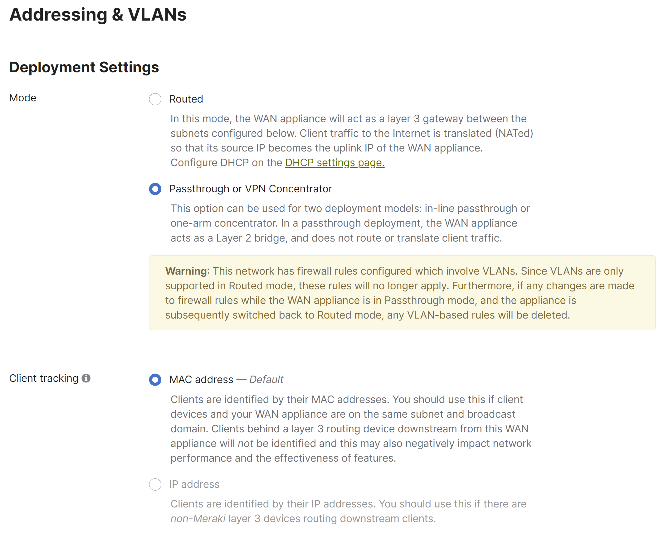
Begin by configuring the MX to operate in VPN Concentrator mode. This setting is found on the Security & SD-WAN > Configure > Addressing & VLANs Page. The MX will be set to operate in Routed mode by default.
-
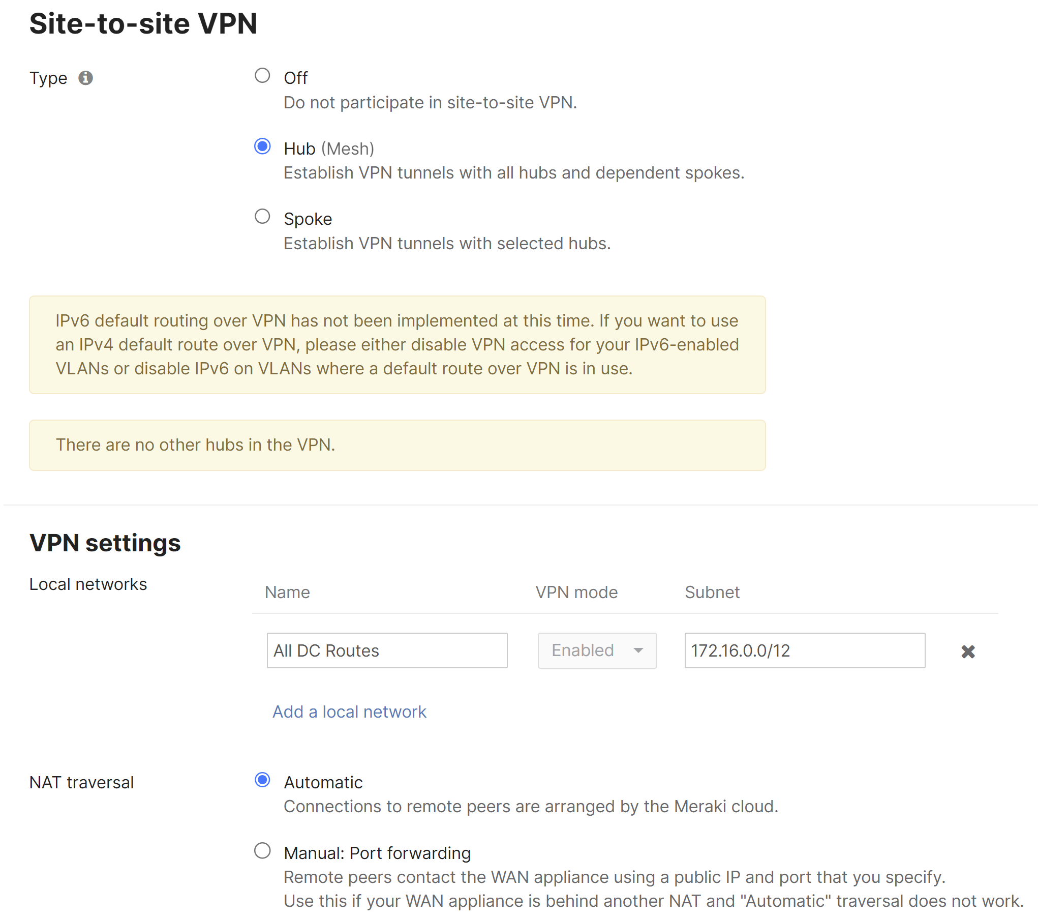
Next, configure the Site-to-Site VPN parameters. This setting is found on the Security & SD-WAN > Configure > Site-to-site VPN page.
- Begin by setting the type to "Hub (Mesh)."
- Configure the local networks that are accessible upstream of this VPN concentrator.
-
For the Name, specify a descriptive title for the subnet.
-
For the Subnet, specify the subnet to be advertised to other AutoVPN peers using CIDR notation
-
-
NAT traversal can be set to either Automatic or Manual: Port forwarding. See below for more details on these two options.
-
An example screenshot is included below:
NAT traversal
Whether to use Manual or Automatic NAT traversal is an important consideration for the VPN concentrator.
Use manual NAT traversal when:
- There is an unfriendly NAT upstream
- Stringent firewall rules are in place to control what traffic is allowed to ingress or egress the datacenter
- It is important to know which port remote sites will use to communicate with the VPN concentrator
If manual NAT traversal is selected, it is highly recommended that the VPN concentrator be assigned a static IP address. Manual NAT traversal is intended for configurations when all traffic for a specified port can be forward to the VPN concentrator.
Use automatic NAT traversal when:
- None of the conditions listed above that would require manual NAT traversal exist
If automatic NAT traversal is selected, the MX will automatically select a high numbered UDP port to source AutoVPN traffic from. The VPN concentrator will reach out to the remote sites using this port, creating a stateful flow mapping in the upstream firewall that will also allow traffic initiated from the remote side through to the VPN concentrator without the need for a separate inbound firewall rule.
For more information regarding Automatic NAT traversal for AutoVPN, please review this document.
Adding warm spare
This section outlines the steps required to configure and implement warm spare (HA) for an MX WAN appliance operating in VPN concentrator mode.
Topology
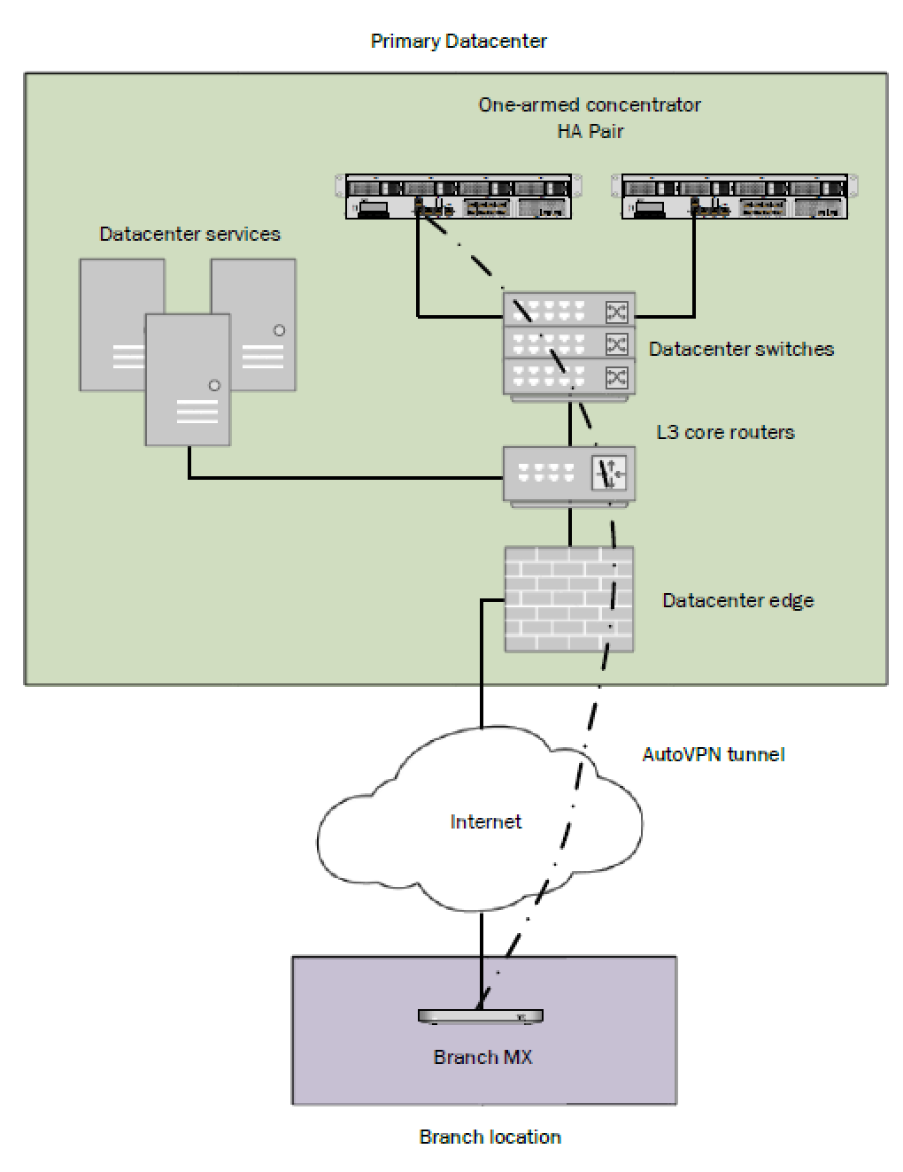
The following is an example of a topology that leverages an HA configuration for VPN concentrators:
Behavior
When configured for high availability (HA), one MX is active, serving as the active, and the other MX operates in a passive, standby capacity. The VRRP protocol is leveraged to achieve failover. Please see here for more information.
Dashboard Configuration
High availability on MX WAN appliances requires a second MX of the same model. The HA implementation is active/passive and will require the second MX also be connected and online for proper functionality.
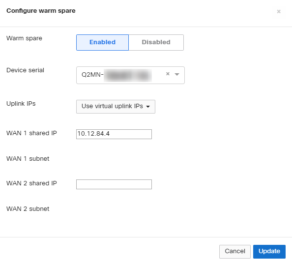
High availability (also known as warm spare) can be configured from Security & SD-WAN > Monitor > Appliance status. Begin by setting Warm Spare to Enabled. Next, enter the serial number of the warm spare MX. Finally, select whether to use MX uplink IPs or virtual uplink IPs.
Uplink IPs
Use Uplink IPs is selected by default for new network setups. In order to properly communicate in HA, VPN concentrator MXs must be set to use the virtual IP (vIP).
Virtual IP (vIP)
The virtual uplink IPs option uses an additional IP address that is shared by the HA MXs. In this configuration, the MXs will send their cloud controller communications via their uplink IPs, but other traffic will be sent and received by the shared virtual IP address.
Configuring OSPF Route Advertisement
MX WAN appliances acting in VPN concentrator mode support advertising routes to connected VPN subnets via OSPF.
Behavior
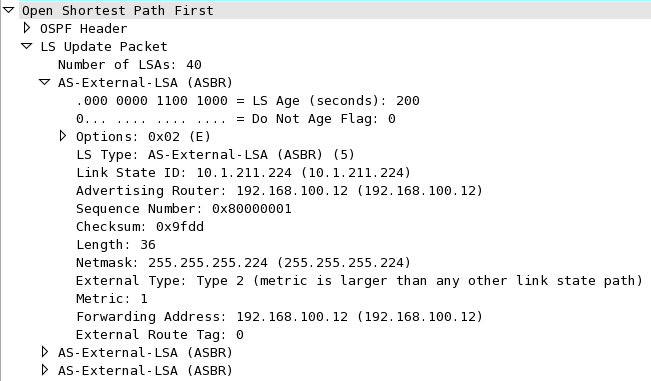
An MX VPN concentrator with OSPF route advertisement enabled will only advertise routes via OSPF; it will not learn OSPF routes.
When spoke sites are connected to the VPN concentrator, the routes to spokes sites are advertised using an LS Update message. These routes are advertised as type 2 external routes.
Dashboard Configuration
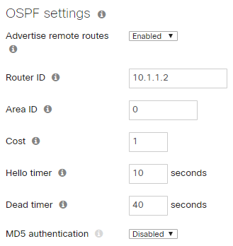
In order to configure OSPF route advertisement, navigate to the Security & SD-WAN > Configure > Site-to-Site VPN page. From this page:
- Set Advertise remote routes to Enabled
- Configure the Router ID
- Configure the Area ID
- Adjust the Cost, if desired
- Adjust the Hello timer, if needed
- Adjust the Dead timer, if needed
- Enable and configure MD5 authentication, if needed
For additional details, please see Using OSPF to Advertise Remote VPN Subnets.
Other Datacenter Configuration
Upstream Considerations
This section discusses configuration considerations for other components of the datacenter network.
Routing
The MX acting as a VPN concentrator in the datacenter will be terminating remote subnets into the datacenter. In order for bi-directional communication to take place, the upstream network must have routes for the remote subnets that point back to the MX acting as the VPN concentrator.
If OSPF route advertisement is not being used, static routes directing traffic destined for remote VPN subnets to the MX VPN concentrator must be configured in the upstream routing infrastructure.
If OSPF route advertisement is enabled, upstream routers will learn routes to connected VPN subnets dynamically.
Firewall considerations
The MX WAN appliance makes use of several types of outbound communication. Configuration of the upstream firewall may be required to allow this communication.
Dashboard & Cloud
The MX WAN appliance is a cloud managed networking device. As such, it is important to ensure that the necessary firewall policies are in place to allow for monitoring and configuration via the Cisco Meraki Dashboard. The relevant destination ports and IP addresses can be found under the Help > Firewall info page in the Dashboard.
VPN Registry
Cisco Meraki's AutoVPN technology leverages a cloud-based registry service to orchestrate VPN connectivity. In order for successful AutoVPN connections to establish, the upstream firewall must allow the VPN concentrator to communicate with the VPN registry service. The relevant destination ports and IP addresses can be found under the Help > Firewall info page in the Dashboard.
Uplink Health Monitoring
The MX also performs periodic uplink health checks by reaching out to well-known Internet destinations using common protocols. The full behavior is outlined here. In order to allow for proper uplink monitoring, the following communications must also be allowed:
-
ICMP to 8.8.8.8 (Google's public DNS service)
-
HTTP port 80
-
DNS to the MX's configured DNS server(s)
Deploying a Routed mode concentrator
Example Topology
An MX VPN concentrator can also be configured to operate in Routed mode. The following diagram shows an example of a datacenter topology with a Routed mode concentrator:
Interface Configuration
The MX WAN appliance being configured as a VPN concentrator should be connected to the "upstream" datacenter infrastructure closer to the network edge using its Internet port, and connected to "downstream" infrastructure closer to the datacenter services using a LAN port.
MX IP Assignment
In the datacenter, an MX WAN appliance can operate using a static IP address or an address from DHCP. MX appliances will attempt to pull DHCP addresses by default. It is highly recommended to assign static IP addresses to VPN concentrators.
Static IP assignment can be configured via the device local status page.
The local status page can also be used to configure VLAN tagging on the uplink of the MX. It is important to take note of the following scenarios:
-
If the upstream port is configured as an access port, VLAN tagging should not be enabled.
-
If the port upstream is configured as a trunk port and the MX should communicate on the native or default VLAN, VLAN tagging should be left as disabled.
-
If the port upstream is configured as a trunk and the MX should communicate on a VLAN other than the native or default VLAN, VLAN tagging should be configured for the appropriate VLAN ID.
Public IP assignment
An MX appliance configured as a Routed mode concentrator can be configured with either a publicly routable IP address or be deployed behind another NAT device within the datacenter topology.
Dashboard Configuration
The Cisco Meraki Dashboard configuration can be done either before or after bringing the unit online.
The following configuration steps will be covered in more detail in the sections below:
-
Configure the MX to operate in Routed mode.
-
Define VLANs and static routes.
-
Configure the Site-to-Site VPN parameters.
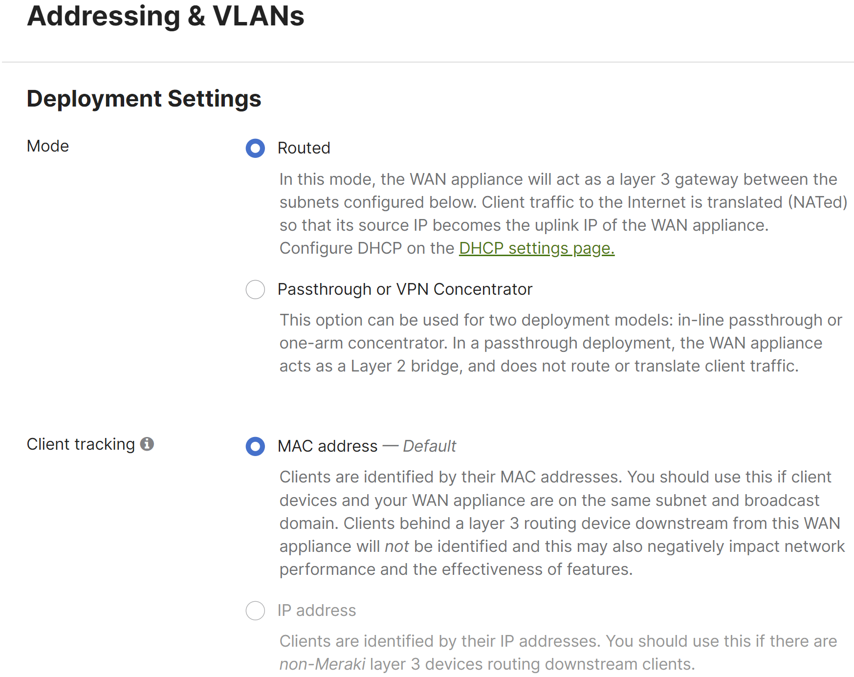
Operating Mode Configuration
Begin by configuring the MX to operate in Routed mode. This setting is found on the Security & SD-WAN > Configure > Addressing & VLANs page.
VLAN and Static Route Configuration
Both VLANs and Static routes can be configured from the Addressing & VLANs page. Both Static routes and VLANs can be advertised into the AutoVPN topology. However, VLANs configured on a Routed mode MX must be unique to each Routed mode MX within the AutoVPN topology.
For a Routed mode concentrator, it is recommended to configure a VLAN with a small subnet for communication between the MX and other downstream infrastructure. Static routes are then used to provide access to other datacenter services downstream.
Defining a VLAN
Begin by navigating to the Security & SD-WAN > Configure > Addressing & VLANs page to define a subnet to be used for communication with other downstream routers.
If VLAN-specific configuration is required for downstream communication out the MX's LAN port, such as tagging traffic with a specific VLAN ID, VLANs must be enabled. First, enable VLANs. Under the Routing heading, check the Use VLANs box to enable VLANs. This allows a VLAN ID to be configured for subnets defined in the Subnets table.
Then, click the Default subnet within the Subnets table. This will bring up the Modify VLAN configuration menu.
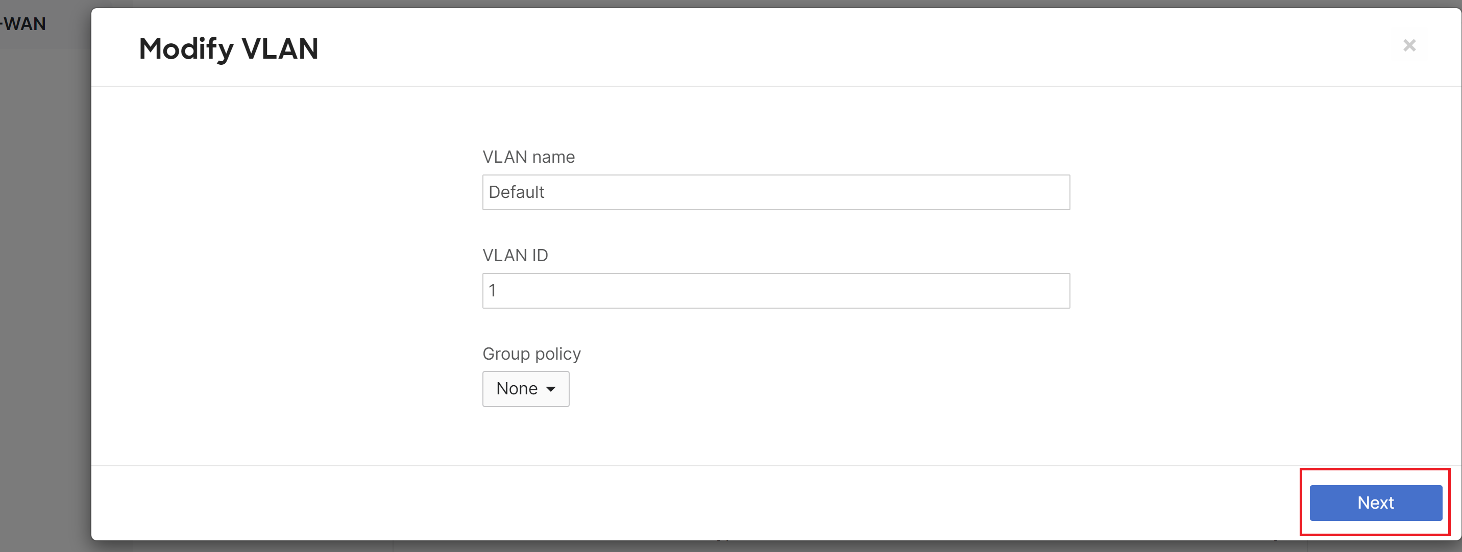
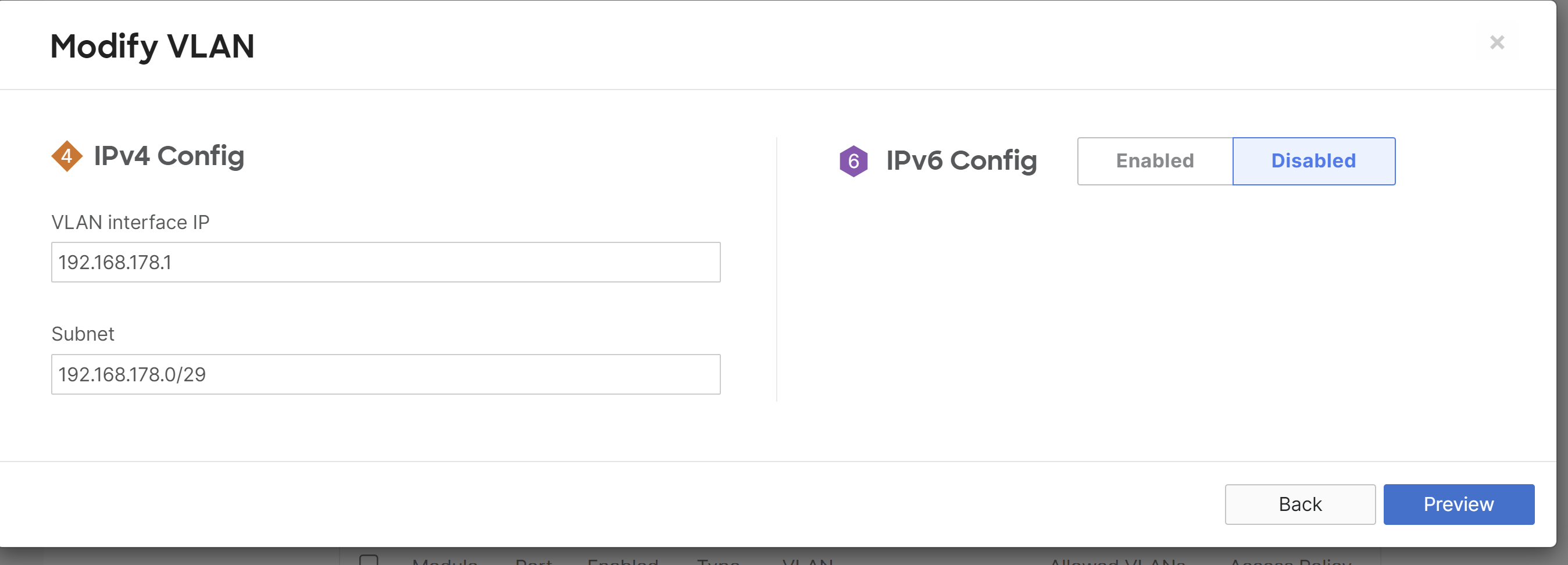
From the VLAN configuration, define the VLAN Name, VLAN ID, Group Policy, VPN mode (if Site-to-site VPN is enabled), IPv4 VLAN interface IP and Subnet, and IPv6 config (if enabled).
The Configure Single LAN configuration menu will be presented if VLANs are disabled. The Modify VLAN configuration menu will be presented if VLANs are enabled. VLAN ID is only configurable from the Modify VLAN configuration menu.
Per-port VLAN Configuration
If VLANs are set to enabled from the Addressing & VLANs page and a VLAN has been defined for communication between the WAN appliance acting as a Routed mode VPN concentrator and downstream routers, it is important to set the LAN port's VLAN configuration correctly for proper bi-directional communication.
In the Per-port VLAN Settings table, click on the LAN port connecting the WAN appliance to the downstream infrastructure to bring up the Configure MX LAN ports menu. From here, set Enabled, Type, Native VLAN, and Allowed VLANs.
Defining Static Routes
To define a static route, begin by navigating to the Security & SD- WAN > Configure > Addressing & VLANs page.
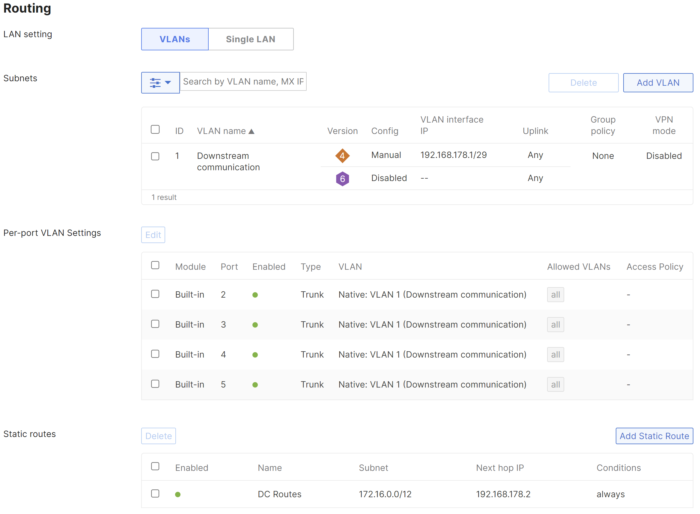
Click on the Add Static Route link in the Static Routes table to open the Add Static Route configuration menu.
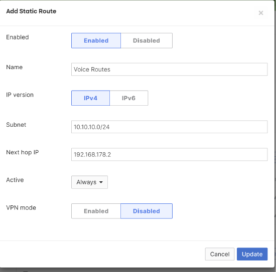
In the Add Static Route configuration menu, define the Name, IP version, Subnet, Next hop IP, Active state, and the VPN mode status.
The VPN mode configuration option on the static route configuration menu will only appear if VPN has already been enabled on the Security & SD-WAN > Configure > Site-to-site VPN page.
Static routes can also be configured to be allowed in the VPN from the Site-to-site VPN page.
Multiple static routes may be configured. An example is included below:
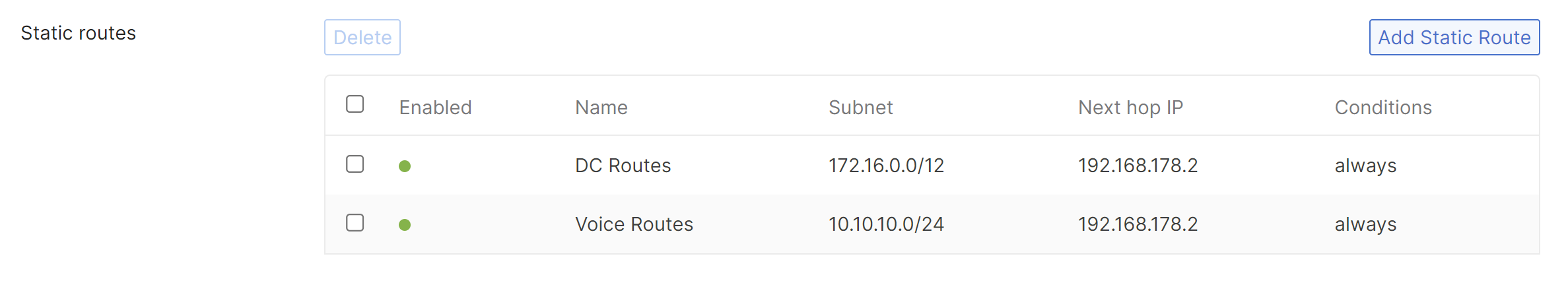
Static routes that are allowed in VPN will always be advertised into AutoVPN. Static routes configured as active While next hop responds to ping and While host responds to ping will be advertised AutoVPN, independent of whether the static route's active condition is met.
Please see here for more information on configuring static routes on Routed mode WAN appliances.
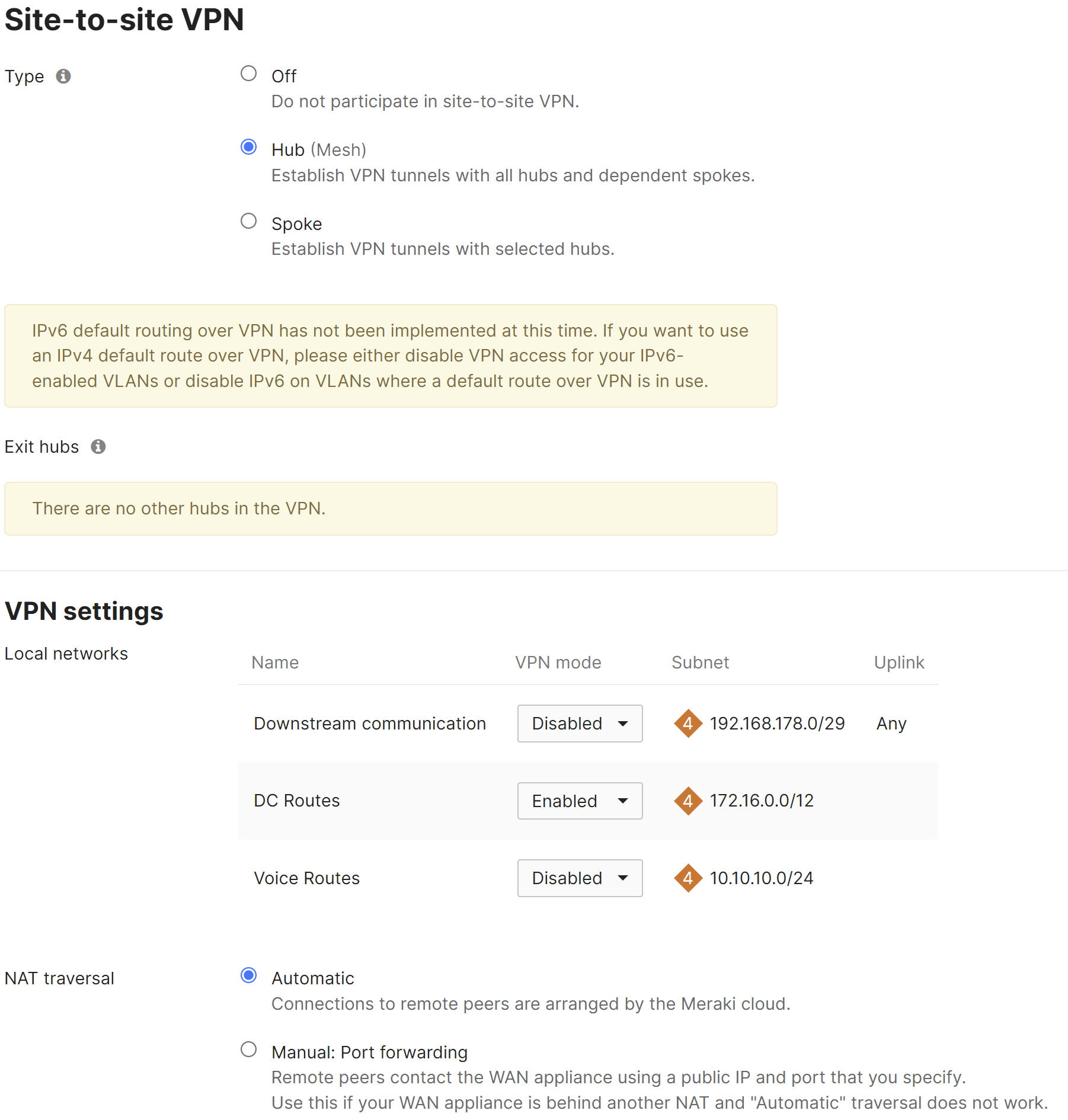
Configure Site-to-site VPN
Site-to-site VPN configuration settings are managed from the Security & SD-WAN > Configure > Site-to-site VPN page. From the site-to-site VPN page, begin by setting the type to "Hub (Mesh)." In the Local networks table, for each subnet that needs to be accessible over VPN, set VPN mode to "Enabled". NAT traversal can be set to either Automatic or Manual: Port forwarding. See below for more details on these two options. An example screenshot is included below:
NAT traversal
Whether to use Manual or Automatic NAT traversal is an important consideration for the VPN concentrator.
Use manual NAT traversal when:
-
There is an unfriendly NAT upstream
-
Stringent firewall rules are in place to control what traffic is allowed to ingress or egress the datacenter
-
It is important to know which port remote sites will use to communicate with the VPN concentrator
If manual NAT traversal is selected, it is highly recommended that the VPN concentrator be assigned a static IP address. Manual NAT traversal is intended for configurations when all traffic for a specified port can be forward to the VPN concentrator.
Use automatic NAT traversal when:
-
None of the conditions listed above that would require manual NAT traversal exist
If automatic NAT traversal is selected, the MX will automatically select a high numbered UDP port to source AutoVPN traffic from. The VPN concentrator will reach out to the remote sites using this port, creating a stateful flow mapping in the upstream firewall that will also allow traffic initiated from the remote side through to the VPN concentrator without the need for a separate inbound firewall rule.
Adding warm spare
This section outlines the steps required to configure and implement warm spare (HA) for an MX WAN appliance operating in Routed mode.
Topology
The following is an example of a topology that leverages an HA configuration for VPN concentrators:
Behavior
When configured for high availability (HA), one MX is active, serving as the active, and the other MX operates in a passive, standby capacity. The VRRP protocol is leveraged to achieve failover. Please see here for more information.
Dashboard Configuration
High availability on MX WAN appliances requires a second MX of the same model. The HA implementation is active/passive and will require the second MX also be connected and online for proper functionality.
High availability (also known as warm spare) can be configured from Security & SD-WAN > Monitor > Appliance status. Begin by setting Warm Spare to Enabled. Next, enter the serial number of the warm spare MX. Finally, select whether to use MX uplink IPs or virtual uplink IPs.
Uplink IPs
Use Uplink IPs is selected by default for new network setups. In order to properly communicate in HA, VPN concentrator MXs must be set to use the virtual IP (vIP).
Virtual IP (vIP)
The virtual uplink IPs option uses an additional IP address that is shared by the HA MXs. In this configuration, the MXs will send their cloud controller communications via their uplink IPs, but other traffic will be sent and received by the shared virtual IP address.
The functionality discussed here is currently only available in beta. To get access to the beta, please contact Meraki Support.
Other Datacenter Configuration
Routing Considerations
The MX acting as a VPN concentrator in the datacenter will be terminating remote subnets into the datacenter. In order for bi-directional communication to take place, the downstream network must have routes for the remote AutoVPN subnets that point back to the MX acting as the VPN concentrator.
In order for traffic received on the LAN side of a Routed mode concentrator to be passed over AutoVPN, traffic must both be sourced from a subnet matching a local VLAN or static route defined on the Addressing & VLANs page of the concentrator and that subnet must be allowed in VPN. If either condition is not met, traffic will not be routed by the MX from the LAN over AutoVPN.
Upstream Considerations
This section discusses configuration considerations for other components of the datacenter network.
Firewall considerations
The MX WAN appliance makes use of several types of outbound communication. Configuration of the upstream firewall may be required to allow this communication.
Dashboard & Cloud
The MX WAN appliance is a cloud managed networking device. As such, it is important to ensure that the necessary firewall policies are in place to allow for monitoring and configuration via the Cisco Meraki Dashboard. The relevant destination ports and IP addresses can be found under the Help > Firewall info page in the Dashboard.
VPN Registry
Cisco Meraki's AutoVPN technology leverages a cloud-based registry service to orchestrate VPN connectivity. In order for successful AutoVPN connections to establish, the upstream firewall must allow the VPN concentrator to communicate with the VPN registry service. The relevant destination ports and IP addresses can be found under the Help > Firewall info page in the Dashboard.
Uplink Health Monitoring
The MX also performs periodic uplink health checks by reaching out to well-known Internet destinations using common protocols. The full behavior is outlined here. In order to allow for proper uplink monitoring, the following communications must also be allowed:
- ICMP to 8.8.8.8 (Google's public DNS service)
- HTTP port 80
- DNS to the MX's configured DNS server(s)
Appendix
Appendix 1: One-armed concentrator operation
A WAN appliance operating in one-armed concentrator mode sends and receives traffic on a singular interface. This interface will always be the the first Internet or WAN port on the unit. A secondary port is not supported when deployed as a VPN concentrator.
It is important to understand the flow of traffic sent across an AutoVPN tunnel while the MX is acting as a one-armed concentrator. In the following scenario we have a host at a branch location trying to load a webpage located in the datacenter, over the site-to-site VPN.
-
The client sends traffic to the private address of the web server to its default gateway, the MX (in Routed mode) at the branch location.
-
The branch MX will look at its routing table and see that the destination IP address is contained within a subnet that is accessible over the Meraki AutoVPN.
-
The branch MX encrypts and encapsulates the data from the client and sends a packet source from its WAN interface, destined for the public IP address and port of the one-armed concentrator at the datacenter that was learned through the VPN registry.
-
This traffic is routed across the Internet to the edge of the datacenter.
-
The edge of the datacenter will NAT the traffic into a private address and send the traffic to the IP address of the one-armed concentrator.
-
The traffic will traverse the network internal to the datacenter and arrive at the one-armed concentrator. The MX will then decrypt and de-encapsulate the traffic and forward the original packet (sent by the client from the branch) upstream.
-
The upstream datacenter infrastructure routes traffic to the server.
-
The server receives the client traffic and sends a response to the client.
-
The response is then routed back through the internal datacenter network to the MX acting as a one-armed concentrator.
-
Upon receiving this response, the one-armed concentrator sees that the destination IP address is contained within a subnet that is accessible over the site-to-site VPN, looks up the contact information for the corresponding AutoVPN peer, encapsulates and encrypts the data, and sends the response on the wire.
-
The response, destined for the public IP and AutoVPN port of the branch MX, is then routed through the datacenter and NAT’ed out to the Internet.
-
The packet is then routed through the Internet to the branch MX.
-
The Branch MX receives the response, decrypts, de-encapsulates, and forwards the server's response downstream.
-
The response then traverses the internal branch network and is received by the client device.
Appendix 2: Routed mode concentrator operation
A WAN appliance operating as a Routed mode concentrator sends and receives encapsulated and encrypted traffic on its WAN interface and sends and receives de-encapsulated and decrypted traffic on its LAN interface.
It is important to understand the flow of traffic sent across an AutoVPN tunnel while the MX is acting as a Routed mode concentrator. In the following scenario we have a host at a branch location trying to load a webpage located in the datacenter, over the site-to-site VPN.
-
The client sends traffic to the private address of the web server to its default gateway, the MX (in Routed mode) at the branch location.
-
The branch MX will look at its routing table and see that the destination IP address is contained within a subnet subnet that is accessible over the Meraki AutoVPN.
-
The branch MX encrypts and encapsulates the data from the client and sends a packet source from its WAN interface, destined for the public IP address and port of the Routed mode concentrator at the datacenter that was learned through the VPN registry.
-
This traffic is routed across the Internet to the edge of the datacenter.
-
The edge of the datacenter will NAT the traffic into a private address and send the traffic to the IP address of the Routed mode concentrator.
-
The traffic will traverse the network internal to the datacenter and arrive at the Routed mode concentrator's WAN interface. The MX will then decrypt and de-encapsulate the traffic.
-
The concentrator will look at its routing table and forward the original packet (sent by the client from the branch) downstream based on the most specific route to the destination address.
-
The downstream datacenter infrastructure routes traffic to the server.
-
The server receives the client traffic and sends a response to the client.
-
The response is then routed back through the internal datacenter network to the MX acting as a Routed mode concentrator.
-
Upon receiving this response, the Routed mode concentrator sees that the destination IP address is contained within a subnet that is accessible over the site-to-site VPN, looks up the contact information for the corresponding AutoVPN peer, encapsulates and encrypts the data, and sends the response on the wire out its WAN interface.
-
The response, destined for the public IP and AutoVPN port of the branch MX, is then routed through the datacenter and NAT’ed out to the Internet.
-
The packet is then routed through the Internet to the branch MX.
-
The Branch MX receives the response, decrypts, de-encapsulates, and forwards the server's response downstream.
-
The response then traverses the internal branch network and is received by the client device.